DC-DC converters: Operating behaviour
In the second and last part of our series on DC-DC converters, we look at the different parameters that describe the operating behaviour of DC-DC converters and their respective dependencies on each other.
In addition to the design variants of DC-DC converters listed in the article “Topologies of DC/DC converters“, many other parameters shape their behaviour. The most important ones are listed and briefly explained below.
Efficiency
The efficiency describes the ratio between the power fed into the converter and the power drawn from the converter and is generally dependent on the respective operating state. Depending on the design, it has its maximum between approx. 30% and 60% of the maximum output power. The efficiency decreases at very low and very high power levels. The responsible mechanisms here are, among others, the self-energy demand, which lowers the efficiency at low power levels, and the ohmic losses, which lower the efficiency at high power levels.
To counteract the drop in efficiency at very low power levels, DC-DC converters can be operated in so-called burst mode, for example. Here, after a few switching cycles, there is a pause in which the load is supplied exclusively from the output filter capacitors. In addition to a more complex design of the control, this can also lead to noise. The efficiency towards high power can be increased, among other things, by overdimensioning the current-carrying elements involved, such as the windings of the transformer or storage choke. Depending on the design, topology and operating condition, efficiencies of well over 95% can be achieved with the switching converters described here.
Secondary-side ripple and noise
In order to specify a DC-DC converter in a meaningful way, information about the behaviour is indispensable. In the following, some parameters often given in data sheets are discussed.
Every DC-DC converter has a high-frequency AC component superimposed on the nominal voltage at the output. This is the result of the charging and discharging of the energy storage devices on the output side with the frequency of the switching operations and is referred to as ripple.
The ripple voltage is typically triangular and depends on the duty cycle of the converter and the dimensioning of the output filter. The greater the inductance of the storage choke and the greater the capacitance of the output capacitor, the lower the ripple voltage. However, these two parameters also have a great influence on the control behaviour explained in the next section. The magnitude of the ripple voltage is usually a few percent of the output voltage.
But the ripple is also superimposed by another, much more complex waveform, the so-called noise. The noise is generated by the switching processes of the active elements such as transistors or diodes in the DC-DC converter, and therefore, just like the ripple voltage, has the switching frequency of the converter as its fundamental frequency. The difference between noise and ripple is the content of high-frequency components in the waveform, which is much higher with noise. This characteristic leads to the fact that the waveform of the noise voltage consists of very narrow peaks. The level of the noise voltage can be influenced by the selection of the active elements, the circuit design, the exact construction of the inductive components (transformer, storage choke) as well as the design of the output filter.
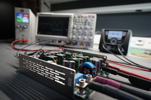
Special attention must be paid to the measurement of the noise voltage, as measurement errors can easily occur here. Due to the high-frequency nature of the switching processes in a DC-DC converter and the high input impedance of common oscilloscopes, coupling by an electric or magnetic field from the converter into the probe of the oscilloscope used for measurement is very easy. This coupling leads to the display of switching peaks, or noise, on the oscilloscope screen, but which are not actually found on the output voltage. The most important way to avoid these measurement errors is not to use the ground terminal typically used with probes, but to lead the ground via a spring directly to the contact provided for this purpose on the probe.
The measurement filter specified in the data sheet of the manufacturer of the DC-DC converter under the item Noise and Ripple must also be simulated as closely as possible.
DC-DC converters with primary-side ripple and noise
Just as on the output voltage, there are also feedback effects from the operation of the DC-DC converters on the input voltage. One example is the input current, which always has an AC component superimposed on its DC component. In buck and buck-derived converters, this is sawtooth to almost rectangular in shape in static operation, depending on the operating mode; in boost converters, it is triangular. The input filter of the converter short-circuits the majority of the input AC current so that it does not penetrate to the outside.
The AC current component that penetrates to the outside and loads the supply of the DC-DC converters causes a voltage drop at the internal resistance of the supply, which can then be measured as an AC voltage component on the input voltage. Just as with noise and ripple on the output voltage, a distinction must be made here between noise and ripple on the input current or, in interaction with the output impedance of the supply, on the input voltage.
The control behaviour of a DC-DC converter
The suppression of the effect of changes in the input voltage on the output voltage is called input voltage regulation or line regulation. Static load regulation or load regulation is a measure of the deviation of the secondary-side voltage from the setpoint voltage as a function of the load. The value is given for a maximum load change from 0% to 100% of the nominal current.
If the load changes abruptly, voltage undershoots or overshoots occur due to the energy stored in the secondary circuit and the physically limited control speed of the DC-DC converters. This is called dynamic control deviation or dynamic control time and is usually specified for a load jump from 20% to 80% and back. The values of interest here are, on the one hand, the maximum deviation from the setpoint voltage and, on the other hand, the time required by the DC/DC converter after the first occurrence of the deviation until the voltage returns to the setpoint window.
The static regulation is influenced by the controller in the DC-DC converter and can reach extremely small values, independent of the topology and other properties of the converter. The decisive factors here are practically only circuit elements that are not within the control loop of the converter, such as the output terminals or lines to the load that are not compensated with external sense lines.
The dynamic regulation, on the other hand, is influenced by many factors, whereby the output filter plays a major role here. Not to be neglected here are the switching frequency of the converter, the ratio between input and output voltage to be covered, and the exact topology of the DC/DC converter.
One of the goals in the development of DC-DC converters is therefore to find the ideal ratio of tolerable noise and ripple, control behaviour, component costs and efficiency for the application.
Other features of DC-DC converters
When looking for a suitable DC-DC converter, other properties must be taken into account in addition to the parameters listed above. For example, heat generation in the power transistors and thus self-heating limits the permissible ambient temperatures. Due to their design, some DC-DC converters require external filters in order to comply with the specified legal regulations for conducted interference emission. If a parallel connection of several converters is necessary for cost reasons or due to lack of availability, these must be designed accordingly. In case of doubt, always consult the manufacturer.
Technical progress in power transistors today enables switching frequencies that were unthinkable years ago. At the same time, however, this requires increasingly complex layouts of the DC-DC converters with very specific properties.