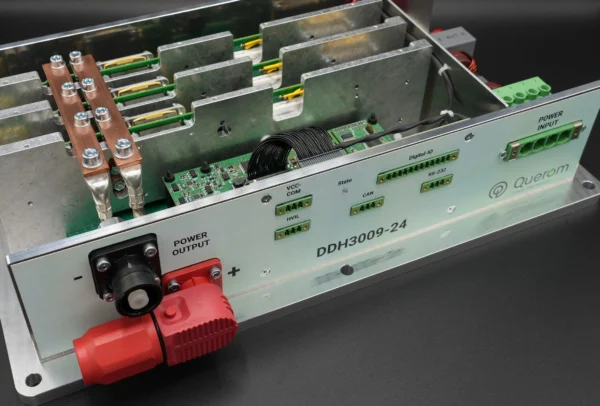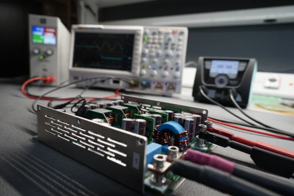
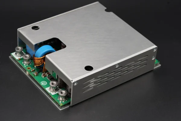
DDL4848-48: Bidirectional 48V DC/DC Converter with 100A and 5kW

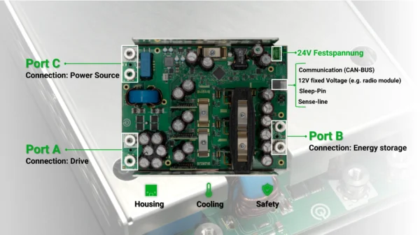
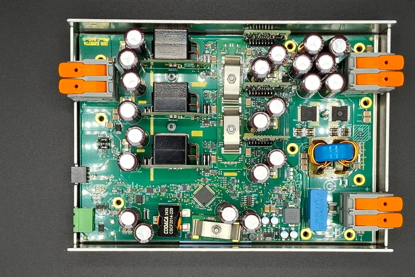
The DDL4848-48 is a non-isolated, bidirectional 48V DC/DC converter in the SELV range for voltages from 30 to 58 V DC. With a rated current of 100 A and a power output of up to 5 kW, it handles bidirectional energy management: In buck mode, it charges batteries and energy storage systems; in boost mode, it feeds energy back into the DC bus. Typical applications include mobile robotics (AGV/AMR) and stationary energy storage systems.

DDL4848-48-C-CAN

bidirectional 48V DC/DC converter DDL4848-48-C-CAN

Technical Specifications:

Power (kW): 5 kW

Input (UHi): 30 – 58VDC

Output (ULo): 0 – 58VDC(UHi > ULo)

Interface: CAN 2.0

Parallel Operation: Yes

Certification:
Safety: EN62368-1
Emission: EN61000-6-4
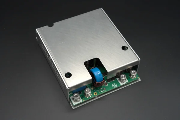
DDL4848-48 at a Glance: Key Features and Applications

The DDL4848-48 is a non-isolated, bidirectional DC/DC converter for the 48V SELV range with a rated current of 100A and a charging power of up to 5kW. We offer it as a core component for 48V DC/DC converter applications in mobile robotics, energy storage systems, and emergency power supplies.

Power-Density

Compact Design

Lightweight

Additional features of the DDL4848-48-C-CAN:

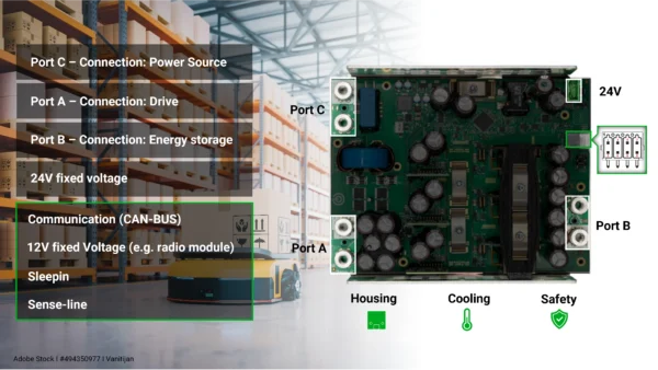
  • 24V Output: An additional 24VDC output with a power rating of 150W can be used to power connected control units, fans, or sensors.
  • Bidirectional 100A / 5kW: Buck and boost operation in a single compact unit – charging power up to 5kW, discharging power up to 5kW
  • SELV-compliant: Operates within the safe voltage range of 30–58 V DC in accordance with EN 62368-1—no risk of electric shock
  • CAN bus interface: Full remote control and monitoring via CAN (standard frame, 500 kbit/s by default)
  • Passive cooling: Heat is dissipated exclusively through the base plate—no fan, no moving parts, no noise
DDL4848-48 - Key Features

Operating modes: Buck mode (charging) and Boost mode (discharging)

The DDL4848-48 operates in two modes: In buck mode (charging), energy flows from Port C or Port A (HV side) to Port B (battery/LV side). In boost mode (discharging), the energy flow reverses—Port B returns energy to the DC bus via Port A.

In buck mode, the converter limits the battery current to the setpoint (max. 100 A, configurable via the SET_1 frame). The voltage at Port B automatically adjusts according to the battery characteristic curve.

In boost mode, Port B supplies a maximum of 85 A of discharge current to the DC bus at Port A. The transition between modes occurs automatically via the control logic (CAN command; analog control is possible as a customer-specific integration)—manual switching is not required.

DDL4848-48 - Operating Mode AGV

Applications: Where is the DDL4848-48 used?

The DDL4848-48 is used wherever bidirectional power flow in the 48V SELV range with high current (up to 100A) is required. We see three key areas where it really shines:

Example of Application of the  DDL4848-48: AGV/AMR & Shuttle Systems

AGV, AMR & Shuttle Systems

Bidirectional energy management between the drive battery and the vehicle electrical system—including regenerative braking energy recovery.

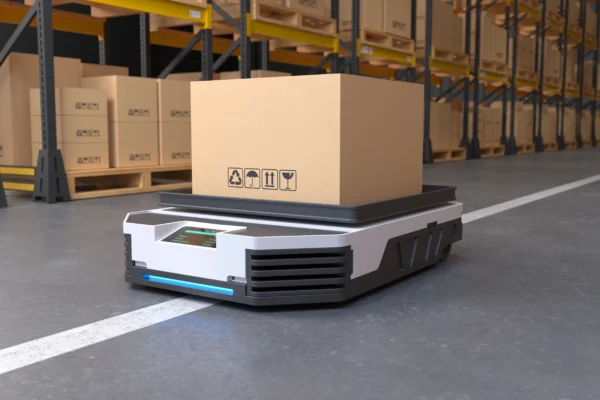
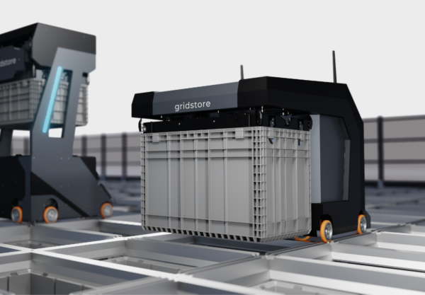
In mobile robots and autonomous vehicles (AGV/AMR), the DDL4848-48 handles bidirectional energy management between the energy storage system and the vehicle electrical system. During acceleration, it operates in buck mode: it charges the battery from the DC bus or supplies power to the drive. During deceleration, it operates in boost mode and feeds the braking energy back into the battery as regenerative current. Gridstore Robotics provides real-world evidence: By using the DDL4848-48 for braking energy recovery, the company achieved a 30% energy savings compared to conventional operation.

© ONOX

Coupling different Electrical System Voltages

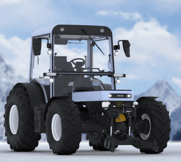
ue to increased performance requirements, agricultural, municipal, and construction vehicles are often equipped with an additional on-board power system operating at a higher voltage.

Typically, power is supplied or charging occurs at only one on-board voltage level. To supply power to the higher voltage level or to charge an installed battery, energy must be transferred between the voltage levels. The DDL4848-48 enables bidirectional coupling of these electrical systems. (Application Example: ONOX – Electric Tractor with removable battery)

For higher voltage levels up to 120 VDC, we recommend the DDL5096-96 (48/96V, 5 kW).

Example of Application of the  DDL4848-48: Uninterruptible Power Supply

Uninterruptible Power Supply (UPS)

Protection of critical loads through immediate switching to battery boost mode in the event of a power outage.

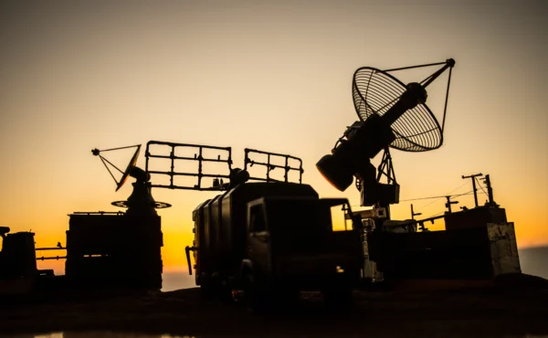
In UPS (Uninterruptible Power Supply) systems, the DDL4848-48 protects critical loads by automatically switching between the battery and the DC bus in the event of a power outage. If the supply voltage at Port C drops to zero, the converter switches to boost mode and supplies the DC bus from the battery. When mains power is restored, it recharges the battery in buck mode. The change in the direction of energy flow is based on the configured voltage levels. Intervention via the CAN bus is not required for this.

Reference Project: Gridstore Robotics – 30% Energy Savings with the DDL4848-48

Gridstore Robotics GmbH

Application: Robot-assisted high-bay warehouse system

Integration: DDL4848-48 as the central power control unit with bidirectional energy flow during braking and venting operations

System Design: Properly Sizing DC/DC Converters

When designing a system using the DDL4848-48, three parameters are critical:

  • Ensure Thermal Connectivity: The converter dissipates heat through its base plate. Ensure that you can dissipate the power loss corresponding to the load profile (efficiency approx. 97%) through the intended mounting surface.
  • Check voltages: Ensure that all voltages occurring during operation at all ports remain within the converter’s permissible ranges (input 30–58 VDC, output 0–58 VDC). If the input voltage falls below the threshold, the converter will shut down.
  • Check power requirements: Design the system based on the actual charging and discharging power requirements. The current setpoint is configurable; the key requirement is that the power demand remains within the converter’s limits (up to 100 A, 5 kW).

Erzählen Sie uns von Ihrem Projekt – wir empfehlen die passende Wandler-Konfiguration für Ihre Spannungslagen und Leistungsklasse. Sprechen Sie Anton Mitterreiter direkt an oder nehmen Sie Kontakt über unser Formular auf.

bidrectional 48V DC/DC converter DDL4848-48

How is the DDL4848-48 controlled?

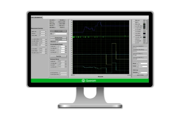
In the standard product, the DDL4848-48 is controlled entirely via the CAN bus (CAN 2.0). The communication interface allows users to set current and voltage setpoints, configure parameters, and read measured values and status messages. This enables a higher-level control system to perform comprehensive diagnostics of the process and respond to various events in real time.

Analog setpoint specification is not included in the standard product, but can be integrated on a customer-specific basis thanks to the modular design.

Comprehensive Firmware Package from Querom Elektronik GmbH

CAN Bus Interface: Documentation for the DDL4848-48

The CAN bus interface of the DDL4848-48 is based on the CAN standard with a standard frame (11-bit identifier) as the default setting and enables full remote control and monitoring. Via CAN, you can control current setpoints and operating modes, configure parameters, and read measured values and status messages in real time. Detailed documentation of all frames is provided in the following sections.

CAN Protocol: Frame Structure and Basic Principles

CAN (Controller Area Network) is a serial bus system conforming to ISO 11898-1, designed for high electromagnetic immunity in industrial environments. In the DDL4848-48, the CAN standard with an 11-bit identifier (standard frame) is the factory default setting; the CONFIG frame can be used to switch to the extended frame (29-bit).

The default operating mode uses a baud rate of 500 kbit/s. The CONFIG frame allows for configuration of 125 kbit/s, 250 kbit/s, 500 kbit/s, and 1 Mbit/s. CAN is particularly well-suited for the DDL4848-48 because multiple devices can share the same bus, communication is prioritized deterministically, and the system is designed to be immune to interference in industrial environments.

Frame Groups: MEAS, SET, STAT, Config, and System at a Glance

The CAN communication of the DDL4848-48 is divided into five frame groups that cover different functions:

Frame GroupCAN-IDs (default)AccessFunction
MEAS (Measurement Values)0x0771 / 0x0772 / 0x0773ReadVoltages, Currents, Temperatures
SET (Setpoints)0x0776 / 0x0777Read/WriteCurrent Setpoints, Power Setpoints, Voltage Setpoints
STAT (Status)0x0780ReadOperating States, Error Codes
Config (Configuration)0x0785 / 0x0786 / 0x0787 / 0x0788 / 0x0789Read/WriteBaud Rate, Frame Format, ID Mapping, CYCLE, SLEEP MODE
System0x0791 / 0x0792 / 0x0793ReadQuerom Device-ID, EMS Serial, Firmware-Version

CAN Configuration: Setting the Address, Baud Rate, and Frame Format

The typical configuration of the DDL4848-48’s behavior involves the following steps:

  1. Terminating resistor: 120 Ω at both ends of the bus (required per ISO 11898-1). If termination is missing, reflections and communication errors will occur (the DDL4848-48 has an integrated terminating resistor).
  2. Set the baud rate: Set the BAUDRATE byte in the CAN_Config frame (0x01 = 1 Mbit/s, 0x02 = 500 kbit/s / default, 0x03 = 250 kbit/s, 0x04 = 125 kbit/s, 0x05 = 100 kbit/s).
  3. Select frame format: Set the FRAME_FORMAT byte to 0x00 (standard, 11-bit) or 0x01 (extended, 29-bit).
  4. Configure CYCLE frame (0x0786): Set the interval for cyclic MEAS telegrams.
  5. Adjust ID mapping (optional): Using CAN_ID_MAP (0x0787), all default CAN IDs can be remapped to custom values. RESET_ID_MAP (0x0788) restores the factory settings.
  6. Note on Parallel Operation: If multiple DDL4848-48 units are used, they are assigned unique, non-conflicting CAN IDs via ID mapping.
  7. Set Current Setpoint: Use SET_1 (0x0776) to specify the desired charging current (0–100 A).
  8. SLEEP MODE as needed: CAN_SLEEP_MODE (0x0789) puts the converter into sleep mode; wake-up via CAN signal.
  9. Note on parallel operation: If multiple DDL4848-48 units are used, they are assigned unique, non-conflicting CAN IDs via ID mapping.

CAN-Bus: Practical Tips for Use

Once the CAN bus has been successfully configured, the DDL4848-48 is very easy to control. The following functions are available:

  • Reading MEAS frames: MEAS_1 (0x0771): Temperatures. MEAS_2 (0x0772): Voltages and currents at Port B and the 24V output. MEAS_3 (0x0773): Voltages and currents at Port A and Port C
  • Set setpoints: Voltage and current values can be set via SET_1 (0x0776). The behavior of the DDL4848-48 can be adjusted and power limits set via SET_2 (0x0777).
  • Analyzing operating status: CAN_STAT_1 (0x0780) provides various status and operating messages as well as a range of error messages.
  • SLEEP MODE as needed: CAN_SLEEP_MODE (0x0789) puts the converter into sleep mode; wake-up via CAN signal.

Technical Specifications: The complete data sheet for the DDL4848-48

The following technical specifications apply to the DDL4848-48, Revision C, as of November 2025. All values are taken from the current manual (Rev. 1.2, November 21, 2025). The individual values are listed in tabular form by topic in the following four subsections.

DDL4848-48-C-CAN

Electrical Parameters: Voltage, Current, and Rated Power

The electrical specifications of the DDL4848-48 are summarized in the following table. All values are taken from Manual Rev. C:

ParameterValueUnitNote
Voltage Range for Port C (Charging Input)10 – 55V DCBeachte Einschränkungen 24V-Ausgang
Voltage Range for Port A (HV Bus)bis 53V DCU_PortA > U-PortB
Voltage Range for Port B (Battery/LV)0 – 53V DCU_PortA > U-PortB
Rated Current, Port B (Buck Mode)100ACharge
Max. Current, Port B (Discharge / Boost)85ADischarge
Max. Charging Power (Buck)5kWaus Manual SET_2 / Kap. 5
Max. Discharge Power (Boost)3kWaus SET_2 PBneg: max –3000W
24V Auxiliary Output150W6,5A continuously
12V Auxiliary Output100mAPower Supply for Sensor / Wireless Module

Efficiency: Efficiency in Buck and Boost Modes

The efficiency η indicates the ratio of output electrical power to input electrical power. In the DDL4848-48, the main converter achieves a minimum efficiency of 97% in buck mode (charging) at currents above 50 A (ILV > 0.5 × ILV,nom). In boost mode (discharging), the minimum efficiency is 94% at IHV > 0.5 × IHV,BUS,nom. The 24V auxiliary output achieves at least 94% efficiency at partial loads exceeding 30%.

The actual efficiency achieved depends on three factors: load factor (η decreases at partial loads below 50%), the voltage difference between Port C and Port B (a smaller difference results in fewer switching losses), and ambient temperature. The minimum values listed apply to normal operation within the permissible temperature range.

Mechanical Specifications: Dimensions, Weight, and Environmental Conditions

The mechanical and environmental specifications for the DDL4848-48 are listed in the table below:

ParameterValueUnit
Dimensions (L × W × H)183 × 142,1 × 45mm
Weight980g
Housing MaterialAluminum
Operating Temperature of the Base Plate0 bis 55°C
Storage Temperature–25 bis 60°C
Thermal Protection Trip (Base Plate)60°C (Latch-off)
Relative Humidity20 bis 95% (nicht kondensierend)
Required Airflow0 (none)m/s – Passivkühlung
Protection ClassNo IP rating (built-in appliance)

SELV Safety Zone and Integrated Protection Functions

SELV (Safety Extra Low Voltage) refers to circuits with voltages of ≤60 V DC, which are considered safe against electric shock in accordance with EN 62368-1. The DDL4848-48 operates exclusively within the SELV range (36–60 V DC)—there is no risk of electric shock when installed as intended.

The converter has the following protection functions, as specified in Manual Rev. C:

  • Over-Temperature Protection (OTP): The converter shuts down as soon as the baseplate temperature exceeds 60°C (latch-off—restart required). Operating near this threshold shortens the service life.
  • Short-Circuit Protection (SCP): Self-resetting: In the event of a short circuit, the control logic limits the current and automatically attempts a restart once the cause has been eliminated.
  • Overvoltage Protection (OVP): Activates when the maximum voltage at Port A or Port B is exceeded—protects the battery and the DC bus.
  • Inrush Current Limitation: Port C has an integrated precharge circuit

Thermal Management: Cooling and Heat Dissipation in the DDL4848-48

The thermal management of the DDL4848-48 is based on passive cooling: Heat is dissipated exclusively through the base plate. Active air cooling is not required. The base plate must be mounted on a surface that has sufficient thermal mass or thermal coupling to dissipate the power dissipation.

The thermal protection trips at a base plate temperature of 60°C and shuts down the converter (latch-off). A restart occurs only after a power cycle. Operation near this threshold is permitted but shortens the service life—we therefore recommend not exceeding a maximum base plate temperature of 50°C during continuous operation.

The power dissipation is calculated based on the efficiency: At a charging power of 5 kW and η = 96%, approximately 200 W of power dissipation occurs in the main converter. The mounting structure must be capable of safely dissipating this amount of heat.

Modular Performance Scaling: Internal Architecture and DDL Series

The DDL4848-48 scales its power output internally using a three-phase switching topology: Three parallel power phases (Phases A, B, C) actively and evenly share the total current—this is the basis for a 100A rated current and high efficiency even with varying load profiles. For systems with different power requirements, we offer additional converters from the DDL series.

Internal Power Balancing: Three-Phase Architecture of the DDL4848-48

Internal current balancing refers to the process in which power paths connected in parallel actively coordinate their current with one another to achieve uniform load distribution and minimize balancing currents. In the DDL4848-48, this occurs internally: The three power phases—A, B, and C—divide the total current of 100 A evenly among themselves—each phase carries a nominal current of approximately 33 A.

Products in the DDL Series

For system designs with different power or voltage requirements, we offer the entire DDL product family. The selection depends on the voltage level, the direction of power flow, and the rated power. Thanks to the modular design, customer-specific requirements can be implemented very quickly:

ModellVoltageDirectionCurrent
DDL3050-4848V (36–60V DC)Unidirektional60A
DDL4848-4848V (36–60V DC)Bidirektional100A Laden / 85A Entladen
DDL2148-2448V (36–60V DC)Bidirektional100A Entladen / 85A Laden
DDL5096-9696V (20-120V DC)Bidirektional50A Laden/ 50A Entladen

What is a bidirectional DC/DC converter?

A bidirectional DC/DC converter is a device that can convert electrical energy in both directions between two DC circuits. Unlike unidirectional converters, which only transfer energy from the input to the output, bidirectional systems actively operate in both directions. In the DDL4848-48, these two directions are called Buck (= charging) and Boost (= discharging). In Buck mode, energy flows from the high-voltage side (HV side, Port C/A) to the low-voltage side (LV side, Port B)—the battery is charged. In boost mode, the energy flow reverses: the battery returns energy to the DC bus. This pair of synonyms—Buck/charging and Boost/discharging—is used consistently throughout this documentation.

What certifications and standards does the DDL4848-48 meet?

The DDL4848-48 complies with the following guidelines and standards as specified in Manual Rev. C. For B2B customers in the EU market, CE conformity is a mandatory requirement for placing the product on the market—the following certifications cover the relevant requirements:

  • EN 62368-1: A safety-oriented standard that establishes requirements for protection against electrical, thermal, mechanical, and other hazards based on a hazard-based safety concept.
  • EN 61000-4-2 (ESD): Electromagnetic Compatibility – Testing of Immunity to Electrostatic Discharge
  • SELV Compliance: Operation exclusively within the Safety Extra Low Voltage range (≤60 V DC) in accordance with IEC 62368-1

We will provide the complete declaration of conformity upon request.

Is the DDL4848-48 electrically isolated?

No. The DDL4848-48 is a non-isolated DC/DC converter—Port C/A and Port B share a common ground reference plane. We offer galvanically isolated versions as custom designs upon request.

What CAN baud rate does the DDL4848-48 support?

The factory default setting is 500 kbit/s. You can use the CONFIG frame to switch to 1 Mbit/s, 250 kbit/s, 125 kbit/s, or 100 kbit/s.

Is the DDL4848-48 SELV-compliant?

Yes. The converter operates exclusively within the SELV range (36–60 V DC, ≤60 V) in accordance with EN 62368-1.

Can the DDL4848-48 be operated without CAN?

Yes. The converter can be configured in advance to operate autonomously without a permanent CAN connection.

How much discharge current does the DDL4848-48 provide?

In boost mode (discharging), the maximum current is 85A up to the maximum bus voltage of 58.5V. In buck mode (charging), the maximum current is 100A.

Querom Elektronik GmbH
Anton Mitterreiter
Mitgründer & Produktmanager

Anton Mitterreiter
Product Manager
a.mitterreiter@querom.de
+49 8743 967197-4